A PID controller consists of the proportional, integral, and derivative blocks connected in parallel. It brings together the characteristics of its building blocks and can therefore be used in all applications.
Output signal and transfer function
The output signal m(t) and the transfer function G(s) of the regulator, placed e(0)=0, are respectively equal to:


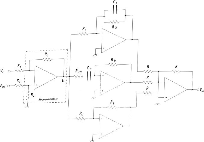
High and low frequency gain limitation
As seen, the ideal PID controller is an improper system, because  when the pulsation ω tends to infinity and when ω=0. To limit the gain, in high and low frequency, the real PID regulator represented in the figure is used, whose transfer function is:

PID Controllers Design
The designer must calculate the value of the KP, KI e KD coefficients so that they meet the specifications of the frequency response (phase and gain margin, bandwidth, etc.) and those of the time response (full error, settling time, delay time, etc.).
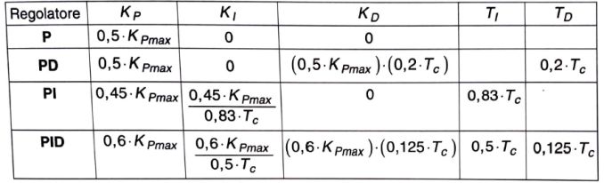
The Ziegler-Nichols method
Among the many methods available, this method is quite widespread in the industrial field. It consists in obtaining the optimal values of the KP, KI e KD parameters by acting on special knobs of the regulator calibrated at the factory.
The phases of optimal regulation are:
- set KP=0, KI=0 e KD=0 and the adjustment ring is closed;
- the value of the KP parameter is gradually increased, after excluding the derivative and integral actions, until the system reaches the limit of stability;
- the value of KP=KPmax is measured, for which the response of the system to the unit step is an oscillation of constant amplitude;
- the pulsation values are measured ωc and the Tc period of the persistent oscillation;
- adjust the other knobs so that the parameters KP, KI and KD take the values shown in the following table.