
Most of the temperature transducers used in industry are analog devices, although digital temperature transducers are also commercially available.
Optimal characteristics for a transducer
- high sensitivity;
- linear output;
- stability of operation over time
To discuss the operation of temperature transducers, we will proceed directly to illustrate some fundamental commercial transducers, without however going too far into the infinite variations that exist of each model.
The PT100 transducer (RTD)
The PT100 transducer, also called RTD thermoresistance, is a precision resistance whose RT value is a function of temperature T.

In general, the nominal value of the resistance of the device is 100 Ω. The RT/T characteristic is linear and increasing:

where:
- RT is the value of the resistance to generic temeperature T;
- R0 is the nominal value of the temperature resistance at 0 °C;
- α=3.85*10-3 °C-1 is the average dimensional coefficient.
In practice, it will be necessary to perform a resistance/voltage conversion. For example, below is an RT/V converter that uses a constant current generator. In this scheme, a voltage regulator is used LM317, capable of delivering a current I≥ 10 mA.

The constant current intensity is equal to:

and for I=10 mA we have:

For example, if T=20 °C, since from the datasheets we get RT=107.79 Ω and imposing I=10 mA, the output voltage is VO=1.077 V.
If the resistance thermometer is placed at a distance from the control system, the connecting wires introduce an additional resistance in the resistance/voltage conversion. In this regard, manufacturers produce three-wire and four-wire resistors suitable for eliminating the error due to the resistance of the connecting wires.
An example
We realize a conditioning circuit for a PT100 temperature transducer able to provide an output voltage between 0 and 5 V when the temperature T varies in the range 0-50 °C.In the proposed shema the integrated INA111 is proposed.
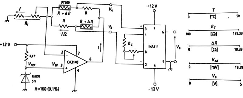
Assuming that the output current from the operational is I=2 mA, each branch of the Wheatstone Bridge is crossed by a current of 1 mA such as not to self-heat the RT resistance thermometers.
In the hypothesis that the CA3140 amplifier can be considered ideal, from the circuit represented in the figure we obtain:

For T=0 °C you have R=RT(0 °C)=100 Ω and for T=50 °C you have RT(50 °C)=119.25 Ω. So you have:

The G gain of the INA111 amplifier and the RG resistance are:

Circuit calibration
It is possible to perform the calibration of the circuit with this procedure:
- act on the trimmer Rl to fix an I =2 mA;
- replace the PT100 with two precision resistors of 100 Ω±0.1% to simulate the operating condition of the transducers for a temperature T =0 °C. In this condition one must have Vo=0 V;
- now replace the two previous precision resistors with two 119.25 Ω to simulate the operation of the transducers for a temperature of T = 50 ° C. In this condition one must have Vo=5 V. In fact, at this temperature, one has RT=100(1+αT)=100(1+3.85*10-3*50)=119.25 Ω
